
KayBee toys sells a remote control mars Rover that has forward
and reverse run by a wired remote control unit. They now sell this for
under $9 I found that with minimal effort I was able to convert the rover
to steerable drive system by installing the MondoTronics
Twin
Motor Gearbox kit($19.95). The Rover will make a nice robot base,internally
there is a built in 4 AA battery pack and lots of extra space for electronics.The
Rover has a flexable drivetrain on the front axle that allows it to climb
over quite significant obstacles. I could tell that this rover was intended
to be sold as two models. One non steering (this kit) and a 2nd that was
a steerable radio control unit.Scientific toys makes this Rover.I do not
know where the radio controlled version was ever sold. There are a few
tips I would like to offer to make this conversion,hopefully it will save
others time and effort.
 Probably
the first place to start is to remove the Solar panel.This is held on by
2 screws under the solar panel sticker itself. These screws are in the
approximate middle of the panel. I used an Exacto knife and cut a tiny
slit in the Panel sticker so that I could remove the screw thru this slit
with a jewelers screwdriver. After removing the screws, slide the panel
aft to remove it.If you peal the Panel sticker off,I doubt you will ever
be able to get it to lay flat again. Inside you will find the 4 AA battery
compartment,and room for electronics. Also access to the 2 backup LED lights
is found here as well.
Probably
the first place to start is to remove the Solar panel.This is held on by
2 screws under the solar panel sticker itself. These screws are in the
approximate middle of the panel. I used an Exacto knife and cut a tiny
slit in the Panel sticker so that I could remove the screw thru this slit
with a jewelers screwdriver. After removing the screws, slide the panel
aft to remove it.If you peal the Panel sticker off,I doubt you will ever
be able to get it to lay flat again. Inside you will find the 4 AA battery
compartment,and room for electronics. Also access to the 2 backup LED lights
is found here as well. The rear axle of the rover will have to be cut to allow installation of
the Twin motor gearbox.The wheels are held onto the axle with a pressed
on steel collar.I was afraid that removing these collars would break the
plastic wheel.Instead I cut the rear axle in half using a dremel tool.I
suppose a hacksaw could be used if you were very careful.In this photo
you can just see the axle broken in half after the cut.
The rear axle of the rover will have to be cut to allow installation of
the Twin motor gearbox.The wheels are held onto the axle with a pressed
on steel collar.I was afraid that removing these collars would break the
plastic wheel.Instead I cut the rear axle in half using a dremel tool.I
suppose a hacksaw could be used if you were very careful.In this photo
you can just see the axle broken in half after the cut. Next
you will have to remove all original motor drive gears and the single motor.
Save the main output gears that drive the Rover wheels you will use these
later. Using my Dremel drill I cut all the gear support stand offs and
motor mounts that were inside the Rover. You can place the Twin motor gearbox
over the opening and get a good idea as to what needs cutting/removal.
You will also need to cut away the rovers right hand gear bay a tiny amount.In
the photo it would be the right side of the bay,as Rover is seen on its
back.This will allow the new gearbox to drop down inside the rover an extra
1/8" It is pretty obvious what needs cutting,just be careful and dont cut
more then necessary.I took small cuts and many trial and error fits of
the new gearbox until I was satisfied with the fit. ( do not be confused
by the 2 motors in the photo,these are from the new gearbox.The photograph
was taken after it was wired)
Next
you will have to remove all original motor drive gears and the single motor.
Save the main output gears that drive the Rover wheels you will use these
later. Using my Dremel drill I cut all the gear support stand offs and
motor mounts that were inside the Rover. You can place the Twin motor gearbox
over the opening and get a good idea as to what needs cutting/removal.
You will also need to cut away the rovers right hand gear bay a tiny amount.In
the photo it would be the right side of the bay,as Rover is seen on its
back.This will allow the new gearbox to drop down inside the rover an extra
1/8" It is pretty obvious what needs cutting,just be careful and dont cut
more then necessary.I took small cuts and many trial and error fits of
the new gearbox until I was satisfied with the fit. ( do not be confused
by the 2 motors in the photo,these are from the new gearbox.The photograph
was taken after it was wired) The
aft section of the Rover will also need to be cut away to allow the Twin
motors to stick out the back of the Rover. I cut just enough away to allow
the motors to fit tightly inside the Rover frame.The motors will stick
out the back about 1/2"Here
is another photo of the Twin gearbox installed,and the wheels slid together.
The motors driveshafts are a bit long for the application.I left mine the
full length,but you could cut yours down in length if you wish.
The
aft section of the Rover will also need to be cut away to allow the Twin
motors to stick out the back of the Rover. I cut just enough away to allow
the motors to fit tightly inside the Rover frame.The motors will stick
out the back about 1/2"Here
is another photo of the Twin gearbox installed,and the wheels slid together.
The motors driveshafts are a bit long for the application.I left mine the
full length,but you could cut yours down in length if you wish. The
biggest problem I had was that the Rovers main drive gear is a bit to large
axle diameter for the twin motor gearbox shafts. I resolved this by cutting
a 1/8" thick circle of wood and drilling a small hole in the center that
will fit tightly onto the Twin motor gearshaft. I then slide the Rovers
Drive wheel onto the shaft,and pressed the wooden lockhub over the shaft.I
used Epoxy to hold the drive gear to the wood hub. The drive wheel has
a raised center section,and I used my dremel to route the center a tiny
bit to allow the wooden hub to fit flat onto the plastic gear. You will
note that if you make the hub to thick it will rub on the large driven
gears on the Rovers main wheels. I am sure there are better ways of doing
this,but could not think of any at the time. I am sorry I dont recall what
drill bit size I used.I myself tried various bits in test wood until I
found one that fit snug.
The
biggest problem I had was that the Rovers main drive gear is a bit to large
axle diameter for the twin motor gearbox shafts. I resolved this by cutting
a 1/8" thick circle of wood and drilling a small hole in the center that
will fit tightly onto the Twin motor gearshaft. I then slide the Rovers
Drive wheel onto the shaft,and pressed the wooden lockhub over the shaft.I
used Epoxy to hold the drive gear to the wood hub. The drive wheel has
a raised center section,and I used my dremel to route the center a tiny
bit to allow the wooden hub to fit flat onto the plastic gear. You will
note that if you make the hub to thick it will rub on the large driven
gears on the Rovers main wheels. I am sure there are better ways of doing
this,but could not think of any at the time. I am sorry I dont recall what
drill bit size I used.I myself tried various bits in test wood until I
found one that fit snug. Here
is a photo of the Drive gears and wooden hubs on the shaft of the Twin
motor gearbox. Note the wood hub is on the outside of the gears.
Here
is a photo of the Drive gears and wooden hubs on the shaft of the Twin
motor gearbox. Note the wood hub is on the outside of the gears. This
is a completed photo of the Gearbox,woodhub and parts assembled. Note in
this photo I painted the woodhub grey,it really does not look bad when
finished. You may be wondering how the Twin gearbox is actually held in
place. When you put the Rovers gearbox cover on,it will press on the frame
of the gearbox and hold the assembly in position nicely. The rear of the
gear box protrudes thru the back of the rover and this is held snugly as
well.
This
is a completed photo of the Gearbox,woodhub and parts assembled. Note in
this photo I painted the woodhub grey,it really does not look bad when
finished. You may be wondering how the Twin gearbox is actually held in
place. When you put the Rovers gearbox cover on,it will press on the frame
of the gearbox and hold the assembly in position nicely. The rear of the
gear box protrudes thru the back of the rover and this is held snugly as
well. Final assembled Rover. At this time I am using the wired controller to
control the Rover. Future plans are to install a Basic Stamp II controller
Final assembled Rover. At this time I am using the wired controller to
control the Rover. Future plans are to install a Basic Stamp II controller
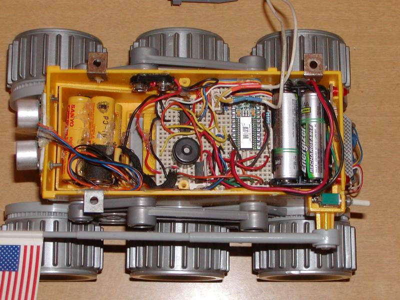
With the
addition of some electronics and a CPU I have given the Rover full autonomous
capabilities. Collision avoidance is not perfect yet, but nothing ever
is. As a test bench it has worked very well for me. I am sorry I never
made a schematic for the circuit, but it is all pretty straight forward.
I have many small circuits breadboarded together inside the rover, and
have wiring diagrams for each seperate circuit. I doubt I will ever get
around to a complete schematic. I have moved on to my 3rd robot which is
much more advanced. A list of the parts and components used are as follows.
In the photographs you will see that I am using the Basic
Micro Atom 24 pin. This CPU is pin for pin compatible with the
Parallax basic stamps and uses the same basic program language. Following
will be software code for the Basic Atom and the Parallax stamp. For begginers
I would have to recommend the Parallax stamp. The only reason being, there
is much more software and hardware support for the Parallax products. Basic
micro is fairly new on the scene and has not developed the user base that
Parallax has.
Code function is as follows: Please do not use my code as
an example of good programming characteristics.
Basically the rover will check its forward sensor, and if nothing is
detected ahead, it will drive the motors forward.
If an object is detected the rover will rotate right 15 degrees, then
proceed ahead again. If it makes 5 turns to the right and is still blocked
then the rover will go into a search pattern.
The rover will rotate its body thru 5 positions and search for the
largest hole around it. When it detects the largest opening, it will drive
forward to that place.
Note: The rotational code for driving the motors is dependant
upon the surface the rover is traveling upon. Turning on a rug takes a
longer time than to turn on a hardwood floor. The motor turn pause
times will have to be edited for your surface.
A better approch would be to use a compass for heading or wheel (track)
sensors to read how much the rover has driven its motors.
Future: There are some referances in the code to future plans.
My next version robot will not just dumbly turn right every time it detects
an object. I also had plans to decide exactly which way to rotate the rover
180 degrees to the rear if it detects itself blocked in all forward directions.
 |
 |
 |
Scientific Toys Mars Explorer info and box photos
If anyone wants to view this material offline, please download the complete webpage in ZIP format. This includes all images and thumbnails. Rover ZIP file 661k
If anyone needs any further help please email me at Admin@MntnWeb.Com